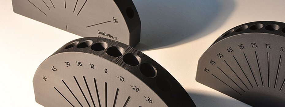
Portable multi-angle measuring instruments are generally used for effect colors and pigments. With a fixed illumination of 45°, measurements are taken at several different angles from the gloss angle. Originally, these geometries were selected for paints or plastics formulated with aluminum pigments. In the meantime, there are a number of new interference pigments that are measured with the same geometries. Although they are visually very different from aluminum pigments, the same classic geometries are used to measure them. Discrepancies to the geometries of the instrumental sampling also occur in visual sampling. On the one hand, this is due to mismatching geometries between the visual and instrumental measurements. On the other hand, the instruments lack geometries with which modern interference pigments can also be analyzed. Experimental instruments such as the GonioViewer Experimental [Fig. 1] bridge these discrepancies with their geometries and support the visual matching of effect pigments.
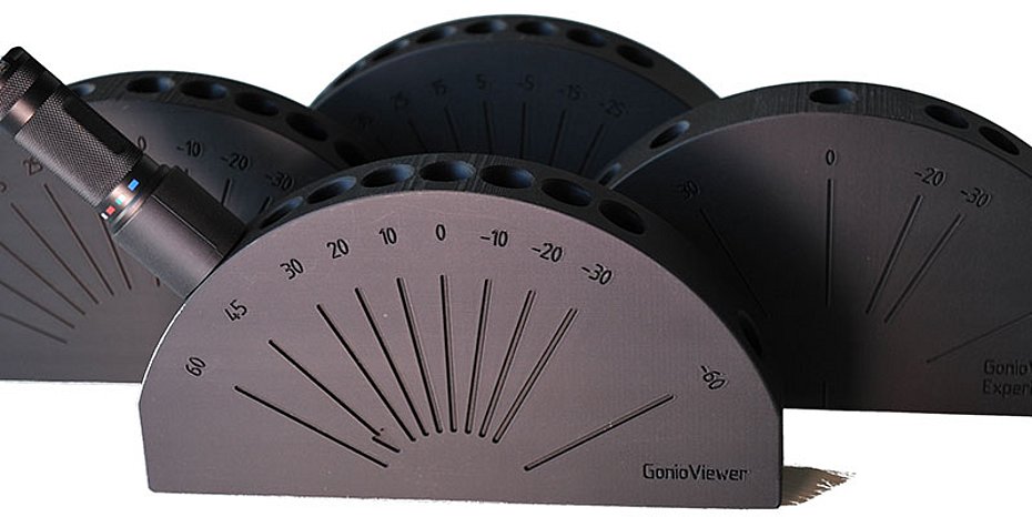
GonioViewer Experimental 01
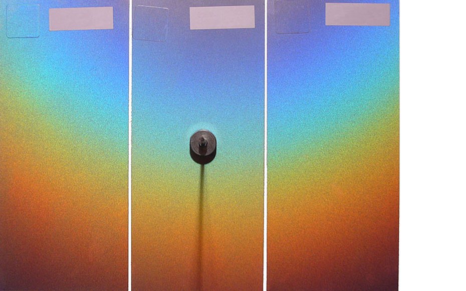
New interference pigments show a color gradient similar to a rainbow. This gradient begins at 30° from the glancing angle with blue-violet via blue, green and yellow to red at 75° from the glancing angle [Fig. 2]. The current measuring instruments measure at 25°, 45° and then at 75° from the glancing angle, i.e. the measured values show the color gradient from blue-green and then to red. The other colors of the gradient are not recorded, although they can be observed visually [Fig. 3].
The GonioViewer Experimental 01 was produced to ensure the visual sampling of these pigments. Like the other GonioViewers, it is produced using 3D printing and measures 23 cm wide and 16 cm high. Holes on the 4 cm wide half-sheet enable illumination and observation. One or two sample sheets can be positioned under the GonioViewer so that comparative observation is also possible. With the GonioViewer Experimental 01, the color gradient of precisely defined geometries can be seen visually. Comparative measurements were made with the Zeiss GK311/M. This measures at different illumination and observation angles, which can be set independently of each other in 5° increments.
GonioViewer Experimental 02
If a sample sheet is viewed at a window or in a light booth, geometries are assumed that do not correspond to the geometry of the measuring instruments. The sample sheet - individually or with a reference sample - is tilted up and down. The starting position is the view into the gloss on the sample sheet, the angle of which is determined by the angle of the lighting. The standard is positioned vertically on the sample sheet between the two. If the angle of illumination in the starting position is 15°, for example, observation takes place at -15°. The difference angle of 30° between the two positions remains the same during the entire observation, i.e. the position of the lighting and the position of the observer do not change.
If the sample sheet is tilted downwards, the normal moves in the direction of the illumination and the illumination angle becomes smaller. The gloss angle also decreases accordingly. If the illumination angle is then 5° and the specular angle correspondingly -5°, the sample sheet is observed at -25° (5° illumination minus 30° difference angle between illumination and observation equals -25° observation equals -20° from the specular angle (= aspecular)). The observation is on the side of the specular angle opposite the illumination (trans position). If the sample sheet is tilted further down, the illumination first moves to the normal and then to the other side of the normal. Accordingly, the gloss angle also changes side to the normal (cis position = illumination and observation are on the same side in relation to the gloss angle).
If the sample sheet is tilted towards the observer, the normal also moves towards the observer. This increases the illumination angle and the corresponding gloss angle relative to the normal. If, for example, the sample sheet is tilted by 5° from the starting position towards the observer, the illumination angle changes from 15° to 20° and the gloss angle from -15° to -20°. The observation angle in the starting position changes from -15° to -10° (difference angle 30° between illumination and observation). The difference angle to the gloss angle is then 10°. If the sample sheet is tilted further to 25° illumination, the angle of difference to the specular angle increases to 20°.
Due to the optical law of light inversion, illumination and observation can be interchanged. If you then compare the geometries when tilting up and down, these geometries are exactly the same, i.e. the same geometries are assumed when tilting up and down. It is therefore irrelevant whether the sample sheet is tilted up or down. The GonioViewer Experimental 02 has holes for observation at the window from -25° to 75° in 10° steps. Starting from a difference angle of 30° (15°/-15° illumination/observation) or 50° (25°/-25°), the color gradient can be observed at an exact angle.
GonioViewer Experimental 03
The angles of the holes in this instrument correspond exactly to the angles of the current multi-angle instruments: Illuminate at 45° and observe at -15°, 15°, 25°, 45°, 75° and 110°. In 2008, ASTM(AmericanSocietyfor Testingand Materials) defined additional geometries as standards for the measurement of interference pigments. In addition to the classic angles, which were defined arbitrarily, a second illumination at 15° and a measurement angle at -15° from the gloss angle were added. These angles were published by the author in the early 1990s on the basis of many tests.
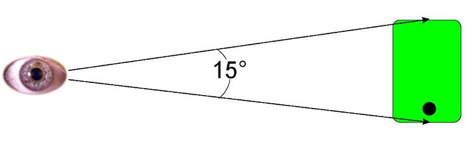
The GonioViewer Experimental 03 has two advantages: When viewing and examining a sample sheet - postcard size, for example - there is an angle of about 15° between its upper and lower edges [Fig. 3]. This angle is greater than the angle between the two measuring angles close to the gloss. Our eye is deceived by colour gradients and cannot recognize colour differences in a gradient. Our visual impression is based on the large area of a sample sheet in contrast to the small measuring field. The GonioViewer Experimental 03 solves this problem with its small and angularly accurate observation area.
GonioViewer Experimental 04
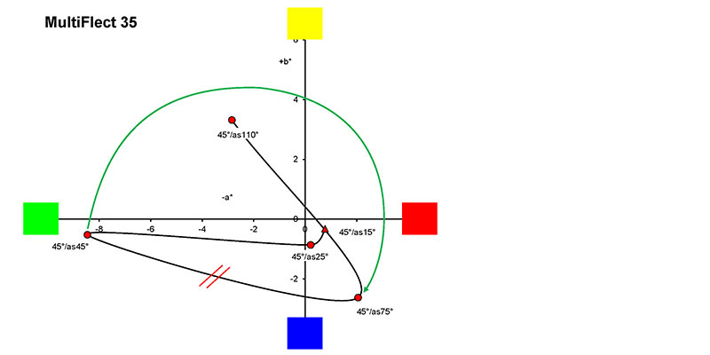
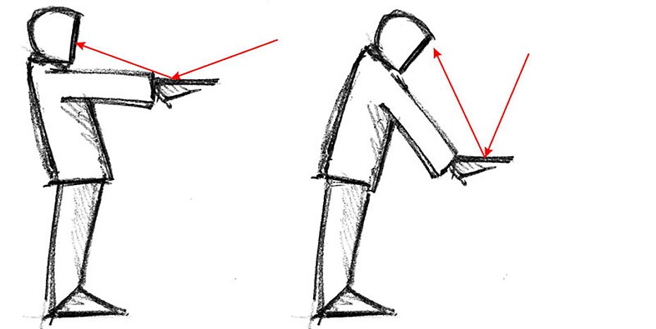
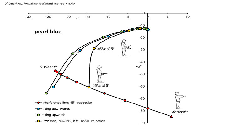
This GonioViewer offers geometries that are taken during a visual inspection of an interference. The sample sheet is viewed with an outstretched arm under flat lighting. The sheet is then moved downwards in parallel, switching to steep lighting. The sheet is always viewed close to the gloss at 15°. This procedure corresponds to the interference law, which describes the dependence of the color on the angle of the incident light [Fig. 4].
The holes of the GonioViewer Experimental 04 are at angles of -60° to 65°, so that an observation is made at 0° with an illumination of 15°, for example. Then the illumination changes in 10° steps up to 65° from the normal. The observations are also made in 10° steps from 0° to -50°. Here too, the sample sheet is viewed with pinpoint and angular accuracy.
GonioViewer Experimental 05
The GonioViewer Experimental 05 corresponds to the GonioViewer 03, with additional holes at 15°, -45° and -75°. These angles correspond to those for sparkle determination on the BYKmac. They are used to illuminate a sample sheet in order to take black and white photos with the camera in the normal position. These are used to calculate the sparkle values.
This GonioViewer 05 can also be used to simulate the second illumination on the MA-98 and MA-T12. It has a hole at 15° for the second illumination. The difference angles at 15°, 45°, 60°, 80° and at -15°, -30°, -45°, -60° can be observed.
GonioViewer Experimental 06
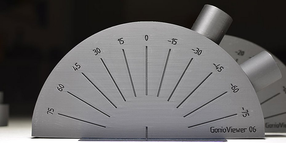
The illumination angles for determining the sparkle values were determined arbitrarily by Byk. The selection was based on the technical and mechanical possibilities in the BYKmac instrument. Therefore, the angles are placed on both sides of the normal: 15°, -45° and -75° from the normal [Fig. 5]. In many cases, there is no difference which side is illuminated. However, there are applied coatings or injection moldings where the direction plays a significant role and differences occur.
For the GonioViewer 06, we have therefore placed the illumination angles on both sides of the normal and also added two angles. With 15°, 30°, 45°, 60° and 75° from the normal respectively, a better picture of the sparkle of the pattern is obtained. It has been shown that the angle combination of 15°, 30° and 60° is better than the combination of 15°, 45° and 75°.
GonioViewer 06 can also be used to adjust the interference and aspecular lines: If illuminated at 15°, 45° and 60° (or also 75°) and 15° from the respective full angle is observed, the interference curve can be seen. The 75° angle is unique and is not realized with any measuring instrument. If you illuminate at 45°, you can see the colour gradient when you move away from the gloss angle. Corresponding difference angles are -30°, -15°, 15°, 30°, 45°, 60°, 75°, 105° and 120° from the specular angle at -45°.
Summary
The current geometries of the portable measuring instruments are based on compilations that are over 30 years old. To date, the suitability of these geometries, particularly for interference pigments, has not been tested. Every day, interference pigments are measured with these instruments without the geometries being scrutinized and the plausibility of the measurement results being checked.
Missing geometries significantly restrict instrumental sampling. The Gonioviewer Experimental can be used to close the gaps for visual sampling. As different requirements are placed on the visual assessment, the versions of the Gonioviewer can be adapted accordingly [Fig. 6]. (OM-2/25)